Drawing Scales are usually 1:50, 1:75, 1:100 and 1:125 and on A4 paper.Ĭan anybody provide me with a standardized listing of architectural entities properties such as name, color, hatch and so forth.Īlso, what is the best procedure to follow in terms of LTSCALE with respect to layer settings.

It will be best if I can follow a set standard (Example BS) that is recognized by architectural firms. However, I don't want to follow an arbitrary naming, coloring or line type system. Package includes: 36 x Pencil Pens 36pcs Musical Note Pencil 2B Standard Round Pencils Piano Notes Writing Drawing Tool Stationery School Student Gift 100. Independently of the scale that we will use to print the drawing we will not scale when we draw on the CAD software. For example if we draw a box with size 20x20x20 cm we will use 20 drawing units for drawing the sides.
#Drawimg standard notes software
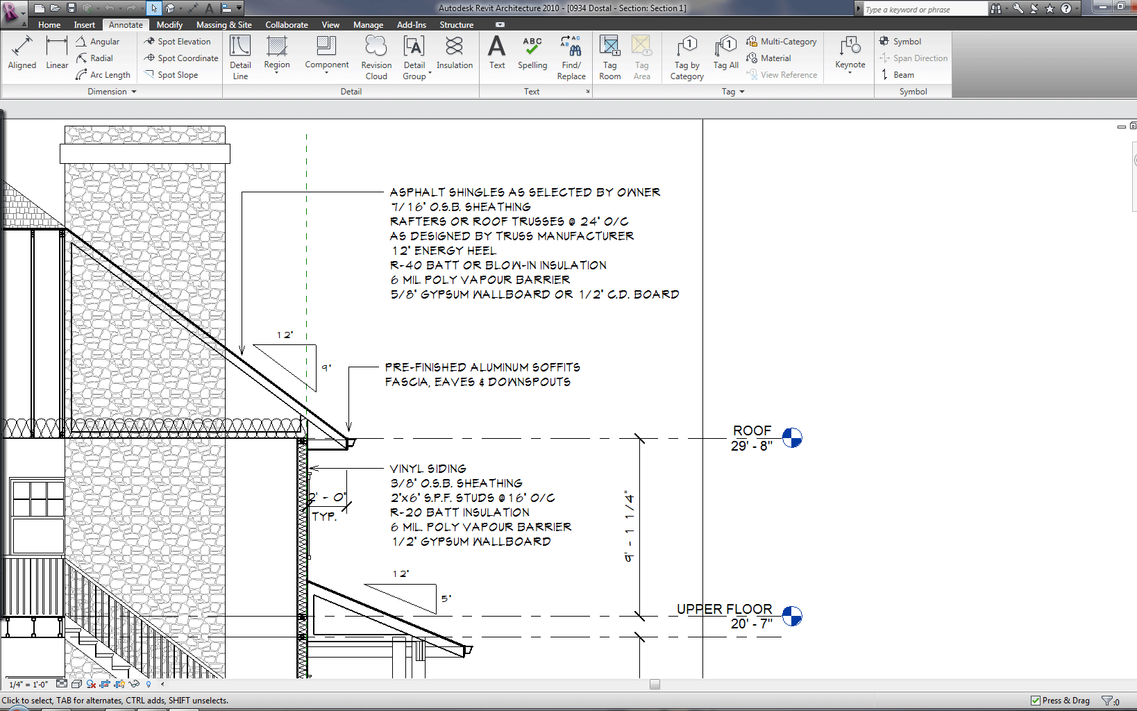
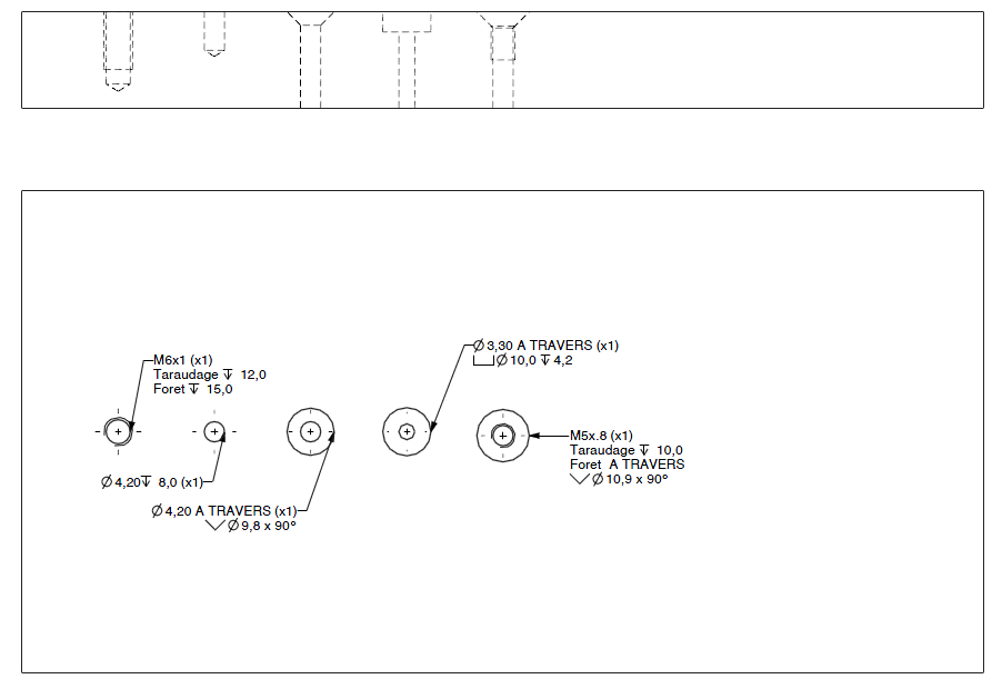
Drawing notes provide information that clarifies the requirements for the item delineated. Standard Printing Scales When drawing using a CAD software we always draw 'real' size (i.e. Moreover, the walls can be 200mm or 150 mm thick, the columns are 200x200 or 150x150 and sometimes 150x200 and the slab is 125mm/150mm to name but a new of the possible configuration. The Standard Drawings show standard details of components and construction techniques to be used in roadworks on Roads and Maritime Services funded infrastructure or infrastructure that will become the property of Roads and Maritime in the future. This Standard defines the practices of revising drawings and. The three components of a set of working drawings. A standard component in this drawing standard is an unaltered component for which no detail drawing is included because the part is to be procured from a source which fabricates that component to that source’s specifications. Although a majority of the symbols and lines are self-explanatory or standard (as described in later modules), a few unique symbols andconventions must be explained for each drawing. to name but a few, also I want to set within the layer the object color, line type, line thickness and so on and if possible which object is on top and which is at the bottom. which a detail drawing is included in the set of working drawings. Engineering drawing notes and legends - Drawings are comprised of symbols and linesthat represent components or systems.

Major Project Signboard (Sheet 1 of 2) This link will open in new window (131KB) C 1002/2B. CEDD Logo This link will open in new window (81KB) C 1002/1I. I am looking for the best ways to create a standard for all my architectural drawings namely I want to have layers set for columns, beams, wall, floor, roof, doors, windows. Drawing List (As of 20 January 2022) This link will open in new window (166KB) SECTION 1 GENERAL.


 0 kommentar(er)
